Abstract
Since the 1980s, oceanic ridges have been proven to be sites at which diagenetic processes (such as serpentinization) result in the generation of natural hydrogen, which escapes through oceanic vents. The water depths in this setting and the location of ocean ridges far offshore would seem to preclude exploitation of this resource, but similar geological contexts are found onshore. Iceland is located along the axis of the Mid-Atlantic Ridge (MAR) and is also a hot spot. As a result, the emerging ridge allows for the study of hydrogen generation within this specific oceanic extensional context. Geothermal energy is well developed in Iceland; accordingly, the presence of natural hydrogen is known based on data from numerous geothermal wells which allowed us to constrain the hydrogen occurrences and compare them with MAR emissions. The results show that H2 contents are high only in the neo-volcanic zone and very low outside the immediate vicinity of this active axis. Values reaching 198 mmol H2/kg fluid have been recorded in Landmannalaugar. Farther north, the gas mixture in the Námafjall area reaches up to 57 vol% hydrogen. These well data are in the same range as those along the MAR. The oxidation of ferrous minerals, combined with the reduction of water, allows for the formation of hydrogen. In Iceland, H2 concentrations in steam seem to be enhanced by both the low concentrations of NaCl in hydrothermal fluids and the strong fracturing of the upper crust, which provides a rapid and constant supply of meteoric fluids for oxidation reactions.
Keywords
Iceland, Natural hydrogen, Oxidation, Mid-Atlantic ridge, Basalts
Introduction
Dihydrogen or H2 (also referred to here as hydrogen) is at the center of many plans for a greener planet. Today, hydrogen is essentially a raw material extracted from CH4 and other hydrocarbons by vapocracking or coal gasification; within the new energy mix, it serves as a fuel for green mobility. However, if H2 production continues to generate CO2, it merely displaces pollutant emissions. Thus, the production of H2 without greenhouse gas (GHG) emission is desirable; this can be achieved via electrolysis or plasma technology, an alternative is the exploration and production of natural H2 [1]. This natural H2 exploration is now active in various places, particularly in intracratonic contexts, after the fortuitous discovery of an accumulation in Mali [2]. In fact, numerous H2 emanations have been observed above Precambrian basins, including in Russia [3-10]. The geological conditions allowing large accumulation and/or production rates remain open to question [11]. However, the first H2 generation zones discovered were not above such basins, but were associated with mid-oceanic smokers [12,13]. Ten years ago, some pioneers made evaluation of the MOR (mid-ocean ridge) but in term of exploration the MOR have not been targeted since the water depths and distances from land in these settings appeared to preclude economic production. In addition, assessments of MOR resources have produced differing results, up to 3 order of magnitude [14] and for some authors the potential resources were low, in comparison of the H2 world consumption, for other ones it is very large and enough have the potential to replace the manufactured hydrogen. Offshore exploration is clearly more expensive than onshore exploration, but the geological characteristics of MORs are similar to those of the ridges present in Iceland or at the Afar Triple Junction, where the Red Sea Ridge and the Aden Ridge outcrop onshore. Here, we revisit MORs and present an analysis of H2 emanations in Iceland. Many wells have been drilled in this country thanks to the geothermal energy industry, and subsurface data are numerous. We mapped these data, compared H2 emanations in Iceland with those at the Mid-Atlantic Ridge (MAR).
Geology of Iceland
Geological Setting
Iceland is part of the North Atlantic Igneous Province and owes its development during the middle Miocene to interaction between the MAR and a hot spot [15]. The island is crossed by a neo-volcanic zone, which is centered on the hot spot and divided into three rift segments (Figure 1): the North Volcanic Zone (NVZ), East Volcanic Zone (EVZ), and West Volcanic Zone (WVZ). The WVZ is the onshore continuation of the Reykjanes Ridge in the southwest. In the north, the NVZ is connected to the Kolbeinsey Ridge by the Tjörnes Fracture Zone (TFZ), a dextral transform fault typical of oceanic ridges. In the south, the South Iceland Seismic Zone (SISZ) is also a transform fault marked by high seismicity (Figure 1). The TFZ, together with the SISZ, accommodates extension due to the presence of the ridge [16].
The simultaneous presence of the MOR and the hot spot has enhanced magmatic activity since the middle Miocene. The crust has a maximum thickness of 30 km in the northernmost, easternmost, and westernmost parts of the island; in contrast, crustal thickness in the center of the rift is approximately 8–10 km [17,18]. The oldest rocks are located in the northwest of the island and are from the Middle Miocene (15–16 Ma), but the most widespread rocks are Plio–Pleistocene in age (Figure 1); 90% of these are basic rocks, most commonly basalts. There are three groups of basalts: tholeiites (olivine 6.6 vol%), transitional alkali (olivine 0.2 vol%), and alkali olivine basalts (14.8 vol%). The tholeiites are mostly found along the axis of the ridge, while the others are mostly found on the margins of the volcanic zone [19]. Some of the rocks found are intermediate, such as basaltic andesites or andesites, while some are acidic, such as rhyolite [20]. Plio–Pleistocene rocks are abundant because of increased magmatic activity at that time. The last glaciation in the Northern Hemisphere started ~100 ka in the Weichselian, with a last glacial maximum occurring ~21 ka [21]. This glacial loading/unloading, which during the last glaciation impacted an Icelandic lithosphere already weakened by the mantle plume, has been proposed to explain the enhanced magmatic activity during the Plio–Pleistocene [22]. The neo-volcanic zone is composed of an en echelon active volcanic system (Figure 1) [23]. Such systems are composed of a main volcano producing basic to acidic lavas and secondary volcanoes with overwhelmingly basaltic lavas. During subglacial eruptions, these volcanoes can produce hyaloclastites and pillow lavas [24]. The hyaloclastites are breccias consisting of glass fragments formed during subglacial eruptions. All of these volcanoes are intersected by fracture and fault swarms [24].
Geothermal Systems
Icelandic geothermal systems can be classified according to the base temperature of their fluids [25], which corresponds to the highest temperature of fluid that can be produced. As fluid transport within the reservoir is mainly convective, this temperature corresponds to the fluids located at the base of the convective cell. Low-temperature systems (i.e., those below 150°C) do not produce electricity efficiently and are thus typically used for heating; these systems appear to be located both inside and outside the neo-volcanic zone. In contrast, high-temperature (HT) systems, whose steam is used to produce electricity, are systematically located inside the volcanic zone (Figure 1), and their base temperature exceeds 200°C. Some poorly explored areas with base temperatures between 150 and 200°C also exist [26,27].
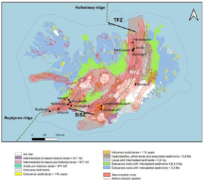
Figure 1: Geological and structural map of Iceland (data from IINH) [17]
Another way to describe high temperature (HT) geothermal systems is to focus on their geological features, including their heat source and heat transfer mode, reservoir characteristics, the fluids, drainage characteristics, cap rock, and surface manifestations. In Iceland, the heat source is of magmatic origin, and heat transfer is assumed to be achieved primarily by the convection of fluids within the crust (Figure 2). In the upper part, the convective fluid is primarily water that circulates within the brittle and highly fractured upper crust, which lies above the magma chamber. A thin, almost purely conductive layer is present between the magmatic body and the upper part; hydrothermal fluids circulate down to this layer. Its low thickness allows for exchange between the volatile components of the magma and the hydrothermal fluids [28]. The “reservoir” is defined as the layer in which convection of water-based fluids occurs and where production may take place. In Iceland, this reservoir is composed primarily of basalts [23] with some rhyolites, which are formed by the partial fusion of basalts. The recharge of the hydrothermal fluids is assumed to be rapid owing to the numerous fracture/fault swarms that have been observed within the Icelandic crust; these structures increase the permeability of the crust. However, there is a strong anisotropy of permeability [29]. Vertical permeability is enhanced by fractures, faults, and damaged zones, whereas horizontal permeability is lower and roughly equal to the basalt bulk permeability. Hence, tectonic characteristics control the downward flow of fluids within hydrothermal systems and allow meteoric fluids or seawater to circulate within the Icelandic crust [30]. The reservoir is covered by layers of hydrothermally altered hyaloclastites [31]. Primary porosity is often infilled by secondary minerals such as smectites. These layers of altered hyaloclastites act as barriers to hydrothermal fluids [31]. However, this seal is not perfect, and leakages are numerous, resulting in the surface manifestations including fumaroles, boiling springs, hot or acidic springs, mud pools, sulfide deposits, siliceous sintering above convective cells, CO2 springs, and travertines (particularly at the rims of hydrothermal basins). Geothermal systems are driven by fluid convective cells. In Iceland, the fluids of these geothermal systems are typically divided into two groups: primary fluids (or reservoir fluids) and secondary fluids [28,32]). The primary fluids are formed by the direct mixing of water with the volatile components of magma. Secondary fluids are produced by water/rock interaction during the ascent of the primary fluids. For example, secondary fluids can oxidize rocks and produce hydrogen, as follows.
H2O + 3FeO → Fe2O3 + H2 (1)
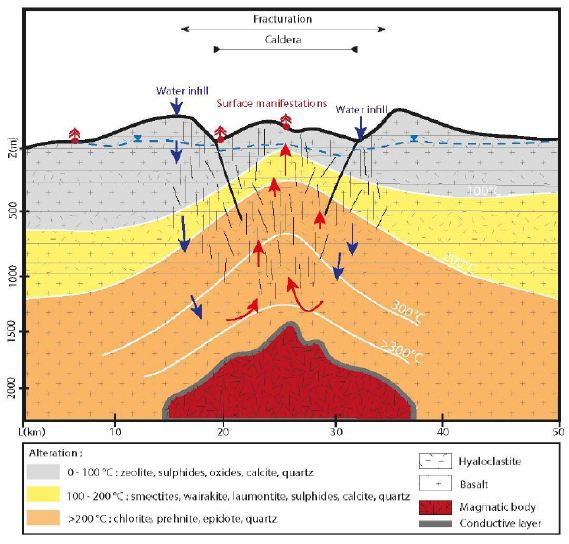
Figure 2: Schematic fluid migration pathway resulting in the geothermal system in Iceland. Within the conductive upper zone, the fracture network enhances the circulation toward the hot conductive layer, in its contact the fluid is warmed up. Water infill is insured by the rain and the ice cap.
Icelandic Hydrothermal Systems
Well Data
We gathered data published from 1950 to 2011 [26, 33-40]. Here, we present a summary of these data for a dozen HT areas in Iceland, including gas compositions, liquid characteristics (such as pH), surface temperatures, and isotopic data (including formation temperature). The fluids were sampled either from the surface (fumaroles and springs) or subsurface (wells), and their temperatures ranged from those of hot steams to those of warm springs. Gas compositions of the vapor phase are listed in Tables 1 and 2 in mmol/kg of fluid and vol%, respectively. In the literature, some data are given in vol%, while others are in mmol/kg H2O. While vol% corresponds to the volume occupied by a chemical species within a mixture, mmol/kg H2O corresponds to the quantity of a species contained in 1000 g of H2O. We tried to convert all of the published values to the same units; however, the available data did not allow us to gather corresponding information such as pressure, temperature, and bulk chemical composition for each site. Thus, it was impossible for us to convert vol% values into mmol/kg H2O and vice versa. Furthermore, the % data values reported sometimes referred to the ratio within the gas present in steam without considering the H2O itself. A more advanced evaluation and comparison between these fluids, from wells and from fumaroles may be fund [41]. To evaluate potential hydrogen production quantitatively, we used kg of H2/year. All available data suggest that hydrogen production varies temporally; thus, the currently available data, mainly sporadic, will allow us to determine only approximate trends.
Table 1: Gas concentrations in mmol/kg of fluid within the steam phase, W is for well and F is for fumarole [26,34,36,39].

Table 2: Gas concentrations, vol% and ppm. G is for non-condensable gas of well discharge [35,37,38,41].

In some areas of note, gas mixtures exhibit remarkable hydrogen contents, reaching 64% and 57% of total gas volume at Namaskard [38] and Námafjall [37], respectively. At Landmannalaugar, H2 concentrations reached a maximum of 198 mmol/kg H2O, which is seven times higher than the concentrations observed within the Ashadze site along the MAR [42]. As seen in (Figure 3), this hydrogen is systematically associated with minor concentrations of CH4 and N2. CO2 is always a major component in the vapor phase (Figures 3 and 4), reaching 93% at Krafla [37]. While hydrogen sulfides are negligible at Krafla [37], H2S concentrations may reach 10% in other areas studied (Figure 4), reaching 22% at Krisuvik [38]. As shown in Tables 1 and 2, H2S concentrations are mostly similar to or lower than H2 concentrations; when they exceed H2 concentrations, as seen at Hellisheidi or Krisuvik, they remain within the same order of magnitude.
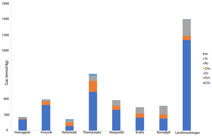
Figure 3: CO2, H2S, H2, CH4, N2, O2, and Ar concentrations (mmol/kg) for nine high- temperature hydrothermal sites (see data in tables)
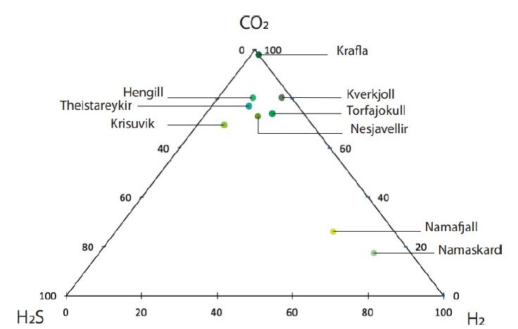
Figure 4: Ternary diagram with relative proportions of CO2, H2S, and H2 for nine high-temperature areas in Iceland [32, 35, 37, 38].
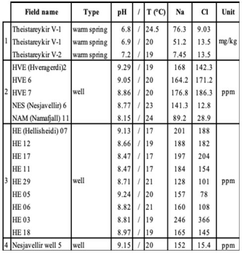
Characteristics of liquid phases are listed in Table 3 for Theistareykir [34], Hveragerdi, Nesjavellir, Námafjall [35, 36] and Hellisheidi [39] only owing to a lack of data for the other sites. The pH of these fluids is between neutral and alkaline and the corresponding surface temperatures do not exceed 25°C. NaCl concentrations for these areas are always lower than 500 ppm.
Table 3: Liquid-phase composition, WS is for warm spring [34-36,39].
Additional Data from Námafjall and Reykjanes Areas
Additional data from these sites mirror the trends exhibited by the published data described above, as seen in Tables 4 and 5. Table 4 contains data from the Námafjall area, which has a basaltic host rock, experiences meteoric water infiltration, and is located inside the neo-volcanic zone. Table 5 contains data from the Reykjanes area, which also has a basaltic host rock and is located inside the neo-volcanic zone but experiences seawater infiltration. Tables 4 and 5 present the gas compositions and liquid characteristics of wells from these areas. The Námafjall site has pH values between 6.6 and 9.7 and surface temperatures between 14 and 25.8°C. The Na and Cl contents for this site are both lower than 500 ppm (Figure 1). The vapor phase is mostly composed of CO2. The H2S and H2 contents here are relatively high, reaching between 12.6 and 121 mmol/kg of fluid. CH4 and N2 contents are non-negligible but never exceed 18 and 115 mmol/kg, respectively. Tables 4 and 5 show that the gas concentration values are variable with time. For instance, in well N°11, H2 has been measured at 31, 48, 55, 80, and 121 mmol/kg H2O over a period of 18 years. These data indicate that this is an active and dynamic system and that monitoring will be necessary before any quantification of flow or annual flux.
Table 4: Námafjall steam phase compositions and liquid characteristics.
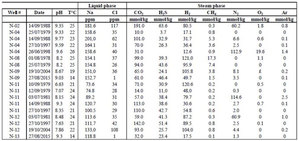
Table 5: Reykjanes steam phase compositions and liquid characteristics.
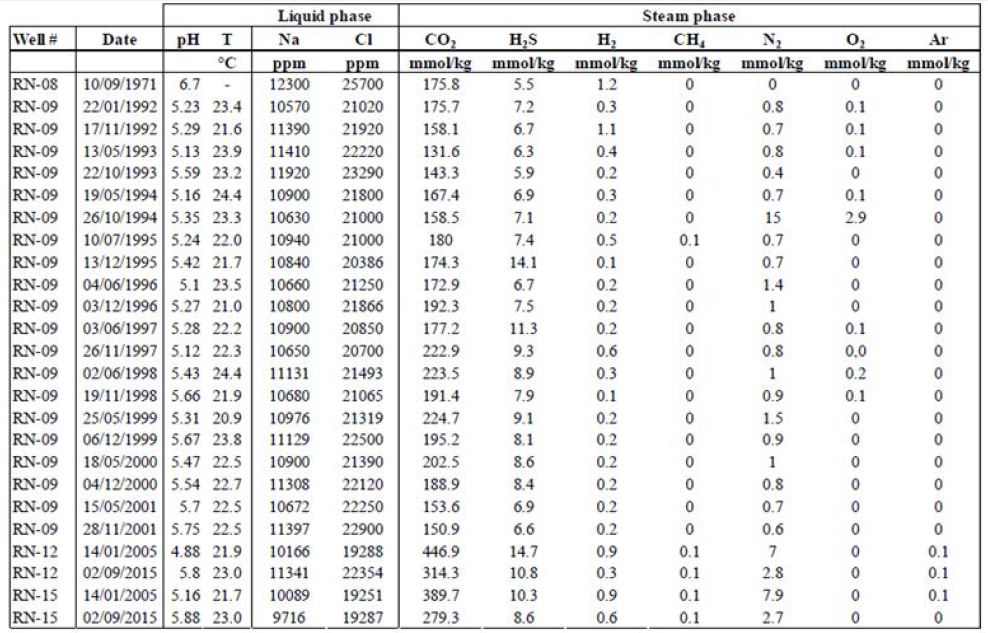
In contrast is the Reykjanes site, the pH values for this site are lower than those for Námafjall and define the fluids as being acidic. Surface temperatures at Reykjanes are between 20.9 and 22.4°C. The fluids from the two sites also differ in terms of their NaCl content; in Reykjanes, NaCl concentrations far exceed 500 ppm. We also found considerable differences in vapor phase composition. While CO2 concentrations are also high at Reykjanes (between 100 and 1000 mmol/kg), H2S and H2 concentrations are lower, rarely exceeding 10 mmol/kg of fluid for H2S and 1 mmol/kg of fluid for H2 .
Isotopic Data
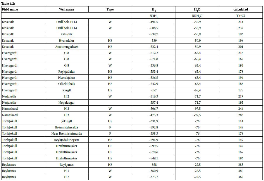
We also collected isotopic data (including 𝛿𝐷 of H2 and H2O and 𝛿13𝐶 of CO2 and CH4) and their corresponding calculated temperatures from the literature. 𝛿𝐷𝐻2 and 𝛿𝐷𝐻2O values have been calculated according to the following equations and are listed in Table 6:
𝛿𝐷𝐻2(‰)=((𝐷/𝐻)𝑒𝑐ℎ/(𝐷𝐻)𝑠𝑡𝑑−1)× 1000 𝑎𝑛𝑑 𝛿𝐷𝐻2𝑂(‰)=((𝐷/𝐻)𝑒𝑐ℎ/(𝐷𝐻)𝑠𝑡𝑑−1)× 1000, (2)
𝛿𝐶𝐶𝑂2(‰)=((𝐷/𝐻)𝑒𝑐ℎ/(𝐷𝐻)𝑠𝑡𝑑−1)× 1000 𝑎𝑛𝑑 𝛿𝐷𝐶𝐻4(‰)=((𝐷/𝐻)𝑒𝑐ℎ/(𝐷𝐻)𝑠𝑡𝑑−1)× 1000. (3)
Table 6.1 & 6.2: Isotopic data and calculated temperature from them, HS = Hot Spring [33,37].

The H2–H2O equilibrium is a geothermometer used to determine the equilibrium temperature reached by H2–H2O, which can be simplified as the formation temperature of hydrogen. Arnason used the H2–H2O geothermometer based on Bottinga’s work (1969) to calculate the hydrogen formation temperature. The fractionation factor used between H2 and H2O is as follows:
∝𝐻2−𝐻20 = [𝐻𝐷𝑂]/[H2O]/([𝐻𝐷]/[𝐻2]). (4)
Sano et al. calculated isotopic temperatures from the difference between 𝛿13C of CO2 and CH4 following Bottinga’s work on the fractionation factor between CO2 and CH4:
∝𝐶𝑂2−𝐶𝐻4 = [𝐷/𝐻]2/[𝐷/𝐻]𝐶𝐻4. (5)
At Námafjall [34], Krisuvik, Hveragerdi, Nesjavellir, Namaskard, Torfajökull, and Reykjanes [33], these isotopic values are between –358.0‰ and –631.0‰, yielding isotopic formation temperatures of 385 and 114°C, respectively. These calculated formation temperatures are represented as a function of H2 concentration in Figure 5.
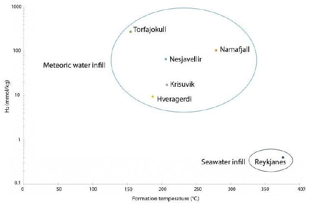
Figure 5: Formation temperature as a function of H2 concentration for six HT areas (data Table 6)
The maximum geothermal gradient inside the rift zone in Iceland is 150°C/km [44]. Based on this gradient and the formation temperatures calculated as above, it is possible to determine the likely depth of hydrogen formation, which tends to occur between 0.8 and 2.5 km. Isotopic data relating to H2O can also provide information about the source of hydrothermal fluids. The 𝛿𝐷𝐻2O values were found to be between –50.9 ‰ and –97.7‰; these negative values indicate that the water within the hydrothermal system is not derived from seawater but is mostly of meteoric origin. The specific value for Reykjanes (–22.5‰) can be explained by the mixing of seawater with water with lower deuterium content, such as meteoric water [33].
Our comparison of data from the literature has allowed us to highlight the most H2-rich areas in Iceland (Figure 6). We considered twelve sites, as follows:
– Theistareykir, Krafla, Námafjall, Namaskard, and Kverkfjoll in the NVZ;
– Landmannalaugar and Torfajökull in the EVZ;
– Hengill, Nesjavellir, Hellisheidi, Krisuvik, and Hveragerdi in the WVZ.
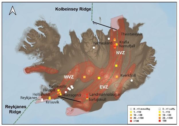
Figure 6: Map of natural H2 emanations in Iceland. Concentration is high in the active volcanic zone and low outside.
Interpretation
Generation of H2
The literature highlights how H2 production is a function of the host rock and its mineralogical composition [45]. The presence of minerals rich in ferromagnesian elements in the host rock allows for the oxidation reaction at the origin of hydrogen generation. In Iceland, the host rock can be divided in three groups: tholeiites, transitional alkali basalts, and alkali olivine basalts. These rocks can contain as much as 15% olivine. [19]. Rhyolite, formed by partial melting of basalts, can be considered a fourth host rock. The presence of olivine, being a ferromagnesian mineral, should allow hydrogen production in Icelandic hydrothermal systems via the oxidation of iron. In addition, in these systems, when the Cl concentration in hydrothermal fluids is low (<500 ppm), the prevailing secondary minerals include the following [36]: pyrite (FeS), pyrrhotite (FeS2), epidote (Ca2(Al2,Fe3+)(SiO4)(Si2O7)O(OH)), and prehnite (Ca2Al2(SiO4)(Si3O10)(OH)2). These minerals are rich in iron and sulfide, which allow for the following reaction:
4FeS + 2 Ca2Al2Si3 O10(OH)2 + 2H2O → 2 FeS2 + 2Ca2FeAl2Si3O12(OH) + 3H2 (6)
For waters with higher Cl concentrations (>500 ppm), the minerals involved include the following: pyrite, epidote, prehnite, magnetite (Fe2+Fe3+2O4), and chlorite. Thus, natural hydrogen is likely produced by the oxidation of ferrous, sulfide-rich minerals, and its concentration is controlled by the mineral–fluid equilibrium, which is controlled by fluid–rock interactions, as proposed by [32]. It is also possible that magmatic degassing and other processes, such as crystallization, can take place during hydrogen production.
H2 Transport
Hydrogen is considered a mobile, reactive, and poorly soluble gas. In fact, its solubility increases above 57°C, which is the temperature at which the minimum solubility of H2 is reached. For P > 30 MPa and 200 < T < 300°C, hydrogen is more easily contained in the gas phase than in the liquid phase [46]. Pressure also plays a role, as greater pressures (i.e., greater depths) lead to greater hydrogen solubilities. Similarly, salinity plays a major role in hydrogen solubility, as described by the “salting-out” effect [47]; in particular, when NaCl concentration increases, hydrogen solubility decreases. As a result, in subsurface at depths greater than a few kilometers, the quantity of H2 in the associated hydrothermal fluid may be large.
Comparison with the Mid-Atlantic Ridge and Its Hydrothermal Systems
Hydrothermal Sites of the MAR
For the last 30 years, hydrothermal smokers along the MAR have been known to be places of natural gas emission, including CH4 and H2 (Figure 7 and Table 7) [12]. In addition to H2 and CH4, these smokers emit primarily CO2, H2S, and trace quantities of Ar and N2 (Figure 8). The maximum hydrogen content recorded to date was 26.5 mmol/kg fluid for the Ashadze site [42]; see location Figure 7).

Figure 7: Mapping of gas emanations along the Mid-Atlantic Ridge
Table 7: MAR H2 concentrations and temperatures [42,48-53].


Figure 8: CO2, H2S, H2, CH4, N2, and Ar concentrations for hydrothermal vents along the MAR [42, 48-53].
The hydrogen gas escapes through smokers located on fractured and faulted basic to ultrabasic basement. These rocks are variably enriched in ferromagnesian elements, and hydrogen is produced by their serpentinization. Typically, a magmatic body in this setting develops into an ultramafic outcrop. The heat coming from the magmatic body warms up the fluids present in the upper part of the crust. The optimum temperature for the serpentinization reaction is between 200 and 350°C [13]. Fluids interact with the rocks such that the ferromagnesian minerals present in the rock (e.g., olivine, Mg1.8Fe0.2SiO4) are hydrated and destabilized. Simultaneously, water is reduced and the ferrous minerals are oxidized into ferric minerals, which leads to the formation of secondary minerals (e.g., serpentine, Mg3Si2O5(OH)4; magnetite, Fe3O4; and brucite, Mg(OH)2) and the liberation of hydrogen [42], as shown below:
3Mg1.8FeO.2SiO4 + 4.1 H2O = 1,5 Mg3Si2O5(OH)4 + 0.9 Mg(OH)2 + 0.2 Fe3O4 + 0.2 H2 (7)
Within approximately the same temperature range, a process of phase separation takes place in the oceanic crust. The vapor phase, which is lighter, rapidly migrates upward through the crust due to the fracture network. In contrast, the liquid phase, which is over-concentrated in chemical elements, remains trapped in pores. While the magmatic body cools, the fluid temperature cools also. The newly established pressure and temperature differences generate a convective fluid cell, which allows the fluid phase to be released through the crust and to the ocean floor [54]. The brine then mixes with colder seawater, and the sulfide elements precipitate to form hydrothermal vents of two types: black smokers and white smokers [55]. The black smokers, such as Rainbow and Logatchev, emit HT (>350°C) anoxic fluids. They are also rich in metallic elements such as iron, manganese, and copper, and their CH4 and H2 concentrations are large. The fluids of white smokers are alkaline and colder, with temperatures as low as 70°C (e.g., Lost City). Even when these smokers are located on the seafloor (i.e., at depths of 3 km), life is prevalent in this environment (Menez [56] and reference inside). The fluids of white smokers are also rich in CaS, CaCO3, and CH4, and their H2 concentrations are higher than those of black smokers.
Geological Commonalities/Differences between Hydrothermal Sites of Iceland and the MAR
This synthesis shows some commonalities between the black smokers along the MAR and Icelandic hydrothermal systems (Figure 9). In particular, their fluid temperatures are similar (Tables 1 and 7), approximatively between 200 and 350°C, and their fluids are alkaline. In both cases, the heat source is magmatic, fluid transfer is ensured by convective cells, and permeability can be attributed primarily to fractures and faults. Furthermore, H2 generation is ensured by the oxidation of ferrous or other mineral-rich materials during H2O reduction. In contrast, the data show some interesting differences between the hydrothermal systems of the MAR and Iceland (Figure 9). In Iceland, all of the H2-rich sites are located in the neo-volcanic zone and, therefore, in an HT area. Landmannalaugar and Torfajökull are located on acidic outcrops of rhyolite, while the other 10 sites are located on intermediate to basic outcrops predominantly comprising basalt. Therefore, unlike the H2-releasing sites along the MAR, which are located on ultrabasic outcrops, H2-rich areas in Iceland are mostly situated on basic outcrops. Furthermore, Icelandic H2-releasing areas are always composed of hydrothermally altered hyaloclastite outcrops, which provide a good cap rock.

Figure 9: Schematic illustration of the Mid-Atlantic Ridge (A) and Iceland (B) illustrating the architecture of the active volcanic zone
Discussion of Key Parameters of Hydrogen Formation in Iceland
Some geological differences exist between the MAR and Icelandic hydrothermal systems; however, we believe that these differences are not the main factors controlling the differences in H2 concentrations between the two settings. The Icelandic context is remarkable in that precipitation rates are high and ice caps are extensive. Most of the water infiltrating the upper crust is meteoric in origin or directly linked to the ice caps [33]. Arnason showed that the residence time of these fluids (i.e., the time since their precipitation) varies significantly, ranging from a few decades to thousands of years (i.e., the last glaciation). Furthermore, the crust here is highly fractured with a very high anisotropy of permeability and hydrogen formation temperatures that are between 200 and 350°C.
Thereby, this synthesis allows us to propose an explanation for the higher H2 concentrations observed for the HT hydrothermal systems in Iceland relative to the MAR systems. We propose the following.
– First, large quantities of water are available in the Iceland systems, which facilitates a rapid and significant water flux for oxidation reactions in the crust.
– Second, owing to the meteoric characteristics of the water flux, NaCl concentrations in the fluid are very low (mostly <500 ppm), resulting in higher hydrogen solubility in the Icelandic fluids. As seen in Figure 4, H2 concentrations are higher in Námafjall, where Cl concentrations are lowest, than in Reykjavik or along the MAR.
– Third, owing to their formation temperatures, Icelandic fluids containing hydrogen are mostly in gaseous form with a minor liquid phase, with the former phase typically containing more hydrogen than the latter [46].
These factors boost hydrogen production such that Icelandic H2 concentrations are higher in many places than those recorded along the MAR.
Conclusion
Our review of the literature allowed us to map the preferred areas for natural hydrogen emissions within Iceland (Figure 6); all of these areas are located within the neo-volcanic zone of this HT geothermal system. The presence of H2-rich zones within the active axis has been also noted for the Goubhet–Asal area, where the Aden Ridge outcrops within the Republic of Djibouti [57]. In the similar context of the Mid-Pacific Ridge, within Socorro Island, H2 values reaching 20% within the vent have been also described [58]. The authors also noted the influence of rainwater and the presence of abiotic CH4. H2-enriched fluids are alkaline and poor in NaCl. Isotopic data and formation temperatures for these fluids can help constrain the conditions of hydrogen formation. The isotopic data show that hydrogen is typically formed at temperatures between 385 and 114°C, which is equivalent to depths between 0.8 and 2.5 km; this makes hydrogen formation a relatively shallow process. Under these conditions, hydrogen formation occurs due to the oxidation of the ferrous minerals of the acidic to basic host rock. In the basic reservoir rocks of Iceland, the primary minerals oxidized during H2 formation include iron sulfides, epidote, and prehnite. Even if this reaction is not considered today as the main one, sulfide oxidation could be particularly important in the formation of H2, particularly when H2S is present. Additionally, H2 can also be produced by the degassing of magma as suggested by Larin [3] and Zgonnik [4]. The H2-producing areas in Iceland and along the MAR appear to be relatively similar; however, the gas concentrations in Icelandic hydrothermal steams tend to be significantly higher than those along the MAR. We posit that this difference is due to the availability of freshwater in Iceland, which does not affect H2 production directly but does affect the solubility of H2, which is higher in freshwater. Finally, it is important to note the high fracture density of the basalt in Iceland, which allows a rapid and constant supply of meteoric waters for reactions. These parameters influence hydrogen concentrations. The presented data also highlight temporal variation in hydrogen concentrations. Although the HT hydrothermal systems considered here appear to be active and dynamic, it would be useful to monitor and quantify the real H2 flux as has been done in Brazil, where structures from the São Francisco Basin emit hydrogen [6,7]. We would not expect to find the various periodicities registered in the monitored fairy circles (e.g., 24 h and sporadic pulses) in the subsurface (where wells are monitored), either directly at the surface or where the soil cover is absent. Nevertheless, further data will be required to characterize changes in H2 flow in the geothermal fluids in Iceland. Finally, the geothermal industry is well established in Iceland, with several important geothermal power plants located in the neo-volcanic zone that allow for electricity production and the heating of farms and other buildings. These power plants release non-condensable gas into the atmosphere, including CO2, H2S, and H2. The Hellisheidi geothermal power plant produced 640 tons of H2 in 2011. In future, the production of natural hydrogen without significant emissions could be possible using classical gas separation processes.
Acknowledgement
The authors gratefully acknowledge Andry Stefansson for the collaboration and the access to the Reykjanes and Namafjall data set, Dr. Dan. Levy and PhD student Gabriel Pasquet, both from E2S UPPA, for many interesting discussions on natural H2. This work is extracted from the Master’s Thesis of Valentine Combaudon, funded by Engie. We thank Isotope Editing for providing specialist scientific editing services for a draft of this manuscript.
References
- Moretti I (2019) H2: energy vector or source?. (L’actualité chimique n° 442, July-Aout, p 15-16.
- Prinzhofer A, Cissé CST, Diallo AB (2018) Discovery of a large accumulation of natural hydrogen in Bourakebougou (Mali). International Journal of Hydrogen Energy 43: 19315-19326.
- Larin N, Zgonnik V, Rodina S, Eric D, Alain P, et al. (2015) Natural molecular hydrogen seepage associated with surficial, rounded depressions on the European craton in Russia. Natural Resources Research. 24: 369-383.
- Zgonnik V (2020) The occurrence and geoscience of natural hydrogen: A comprehensive review. Earth-Science Reviews 243.
- Zgonnik V, Beaumont V, Deville E, Nikolay L, Daniel P, et al. (2015) Evidence for natural molecular hydrogen seepage associated with Carolina bays (surficial, ovoid depressions on the Atlantic Coastal Plain, Province of the USA). Progress in Earth and Planetary Science 2.
- Prinzhofer A, Moretti I, Francolin J, Cleuton P, Angélique D’A, et al. (2019) Natural hydrogen continuous emission from sedimentary basins: The example of a Brazilian H2-emitting structure. International Journal of Hydrogen Energy 44: 5676-5685.
- Moretti I, Prinzhofer A, Françolin J, Cleuton P, Maria R, et al. (2021) Long-term monitoring of natural hydrogen superficial emissions in a brazilian cratonic environment. Sporadic large pulses versus daily periodic emissions. International Journal of Hydrogen Energy 46: 3615-3628.
- Moretti I, Brouilly E, Loiseau K, et al. (2021) Hydrogen Emanations in Intracratonic Areas: New Guidelines for Early Exploration Basin Screening. Geosciences 11.
- Frery E, Langhi L, Maison M, et al. (2021) Natural hydrogen seeps identified in the North Perth Basin, Western Australia. International Journal of Hydrogen Energy 46: 31158-31173.
- Boreham CJ, Edwards DS, Czado K, Rollett N, Wang L, et al. (2021) Hydrogen in Australian natural gas: occurrences, sources and resource. Journal of the Australian Production and Petroleum Exploration Association 61.
- Klein F, Tarnas J, Bach W (2020) Abiotic Sources of Molecular Hydrogen on Earth. Elements 16: 19-24.
- Charlou JL, Donval JP, Fouquet Y, Jean-Baptiste P, Holm N (2002) Geochemistry of high H2 and CH4 vent fluids issuing from ultramafic rocks at the Rainbow hydrothermal field (36°14’N, MAR). Chemical Geology 191: 345-359.
- Cannat M, Fontaine F, Escartin J (2010) Serpentinization and associated hydrogen and methane fluxes at slow spreading ridges. Advancing Earth and Space Science.
- Worman SL, Pratson J, Karson, Schlesinger W (2020) Abiotic hydrogen (H2) sources and sinks near the Mid-Ocean Ridge (MOR) with implications for the subseafloor biosphere. Proceedings of the National Academy of Sciences of the United States of America.
- Martin E, Paquette JL, Bosse V, Ruffet G, Tiepolo M, (2011) et al. Geodynamics of rift–plume interaction in Iceland as constrained by new 40Ar/39Ar and in situ U–Pb zircon ages. Earth and Planetary Science Letters 311: 28-38.
- Garcia S, Arnaud N, Angelier, J, Françoise B, Catherine H, et al. (2003) Rift jump process in Northern Iceland since 10 Ma from 40Ar/39Ar geochronology. Earth and Planetary Science Letters 214: 529-544.
- IINH (2020) – Metadatas and download https://en.ni.is/node/27919
- Björnsson A (1985) Dynamics of crustal rifting in NE Iceland. Journal of Geophysical Research: Solid Earth 90: 10151-10162.
- Jakobsson SP (1972) Chemistry and distribution pattern of recent basaltic rocks in Iceland. Lithos 5: 365-386.
- Sigmundsson F, Einarsson P, Hjartardóttir ÁR, Vincent D, Kristín J, et al. (2021) Geodynamics of Iceland and the signatures of plate spreading. Journal of Volcanology and Geothermal Research 391.
- Bourgeois O, Dauteuil O, Vliet‐lanoë BV (2000) Geothermal control on flow patterns in the Last Glacial Maximum ice sheet of Iceland. Earth Surface Processes and Landforms: The Journal of the British Geomorphological Research Group 25: 59-76.
- Garcia S, Angelier J, Bergerat F, Catherine H, Olivier D, et al. (2008) Influence of rift jump and excess loading on the structural evolution of northern Iceland. Tectonics. 27.
- MORTENSEN, A. Geological mapping in volcanic regions: Iceland as an example. Short Course on Conceptual Modelling of Geothermal Systems, organized by UNU-GTP and LaGeo, in Santa Tecla, El Salvador, 2013.
- Gudmundsson A. (2000) Dynamics of volcanic systems in Iceland: example of tectonism and volcanism at juxtaposed hot spot and mid-ocean ridge systems. Annual Review of Earth and Planetary Sciences 28: 107-140.
- Bodvarsson G (1961) Physical characteristics of natural heat resources in Iceland. Jökull 11: 29-38.
- Ármannsson H, Benjamínsson J, Jeffrey A (1989) Gas changes in the Krafla geothermal system, Iceland. Chemical Geology 76: 175-196.
- Ármannsson H (2016) The fluid geochemistry of Icelandic high temperature geothermal areas. Applied Geochemistry 66:14-64.
- Arnórsson S, Stefánsson A, Bjarnason, JÖ (2007) Fluid-fluid interactions in geothermal systems. Reviews in Mineralogy and Geochemistry 65: 259-312.
- Árnason K (2020) New Conceptual Model for the Magma-Hydrothermal-Tectonic System of Krafla, NE Iceland. Geosciences 10.
- Pope EC, Bird DK, Arnorsson S, et al. (2016) Hydrogeology of the Krafla geothermal system, northeast Iceland. Geofluids 16: 175-197.
- Thien BMJ, Kosakowski G, Kulik DA (2015) Differential alteration of basaltic lava flows and hyaloclastites in Icelandic hydrothermal systems. Geothermal Energy 3.
- Stefánsson A (2017) Gas chemistry of Icelandic thermal fluids. Journal of Volcanology and Geothermal Research 346: 81-94.
- Arnason B (1977) The hydrogen-water isotope thermometer applied to geothermal areas in Iceland. Geothermics 5: 75-80.
- Ármannsson H, Gíslason G, Torfason H (1986) Surface exploration of the Theistareykir high-temperature geothermal area, Iceland, with special reference to the application of geochemical methods. Applied geochemistry 1: 47-64.
- Arnórsson S, Grönvold K, Sigurdsson S (1978) Aquifer chemistry of four high-temperature geothermal systems in Iceland. Geochimica et Cosmochimica Acta 42: 523-536.
- Arnórsson S, Gunnlaugsson E (1985) New gas geothermometers for geothermal exploration—calibration and application. Geochimica et Cosmochimica Acta 49: 1307-1325.
- Sano Y, Urabe A, Wakita H, Hitoshi C, Hitoshi S (1985) Chemical and isotopic compositions of gases in geothermal fluids in Iceland. Geochemical journal 19: 135-148.
- Sigvaldason GE (1966) Chemistry of thermal waters and gases in Iceland. Bulletin Volcanologique 29: 589-604.
- Stefánsson A, Arnórsson S, Gunnarsson I, Hanna K, Einar G (2011) The geochemistry and sequestration of H2S into the geothermal system at Hellisheidi, Iceland. Journal of Volcanology and Geothermal Research 202: 179-188.
- Arnórsson S (1986) Chemistry of gases associated with geothermal activity and volcanism in Iceland: A review. Journal of Geophysical Research: Solid Earth 91: 12261-12268.
- Combaudon V, Moretti I, Kleine B, Stefansson A (2021) Hydrogen emissions from hydrothermal fields in Iceland and comparison with the Mid-Atlantic Ridge, Submitted to International Journal of Hydrogen Energy.
- Charlou JL, Donval JP, Konn C, et al. (2010) High production and fluxes of H 2 and CH 4 and evidence of abiotic hydrocarbon synthesis by serpentinization in ultramafic-hosted hydrothermal systems on the Mid-Atlantic Ridge. GMS 188: 265-296.
- Bottinga Y (1969) Calculated fractionation factors for carbon and hydrogen isotope exchange in the system calcite-carbon dioxide-graphite-methane-hydrogen-water vapor. Geochimica et Cosmochimica Acta 33: 49-64.
- Flóvenz ÓG, Saemundsson K (1993) Heat flow and geothermal processes in Iceland. Tectonophysics 225: 123-138.
- Klein F, Bach W, Mccollom T (2013) Compositional controls on hydrogen generation during serpentinization of ultramafic rocks. LITHOS 178: 55-69.
- Bazarkina EF, Chou IM, Goncharov AF (2020) The Behavior of H2 in Aqueous Fluids under High Temperature and Pressure. Elements: An International Magazine of Mineralogy, Geochemistry, and Petrology 16: 33-38.
- Lopez-lazaro C, Bachaud P, Moretti I, et al. (2019) Predicting the phase behavior of hydrogen in NaCl brines by molecular simulation for geological applications. Prédiction par simulation moléculaire des équilibres de phase de l’hydrogène dans des saumures de NaCl pour des applications géologiques. Bulletin de la Société Géologique de France 190.
- Reeves EP, Mcdermott JM, Seewald JS (2014) The origin of methanethiol in midocean ridge hydrothermal fluids. Proceedings of the National Academy of Sciences 111: 5474-5479.
- Proskurowski G, Lilley MD, Kelley DS, et al. (2006) Low temperature volatile production at the Lost City Hydrothermal Field, evidence from a hydrogen stable isotope geothermometer. Chemical Geology 229: 331-343.
- Kelley DS, Karson JA, Früh-green GL, et al. (2005) A serpentinite-hosted ecosystem: The Lost City hydrothermal field. Science 307: 1428-1434.
- James RH, Elderfield H, Palmer MR (1995) The chemistry of hydrothermal fluids from the Broken Spur site, 29 N Mid-Atlantic Ridge. Geochimica et Cosmochimica Acta 59: 651-659.
- Charlou JL, Donval JP, Douville E, et al. (2000) Compared geochemical signatures and the evolution of Menez Gwen (37 50′ N) and Lucky Strike (37 17′ N) hydrothermal fluids, south of the Azores Triple Junction on the Mid-Atlantic Ridge. Chemical geology 171: 49-75.
- Campbell AC, Palmer MR, Klinkhammer GP, et al. (1988) Chemistry of hot springs on the Mid-Atlantic Ridge. Nature 335: 514-519.
- Coumou D, Driesner T, Weis P, et al. (2009) Phase separation, brine formation, and salinity variation at Black Smoker hydrothermal systems. Journal of Geophysical Research: Solid Earth 1143.
- Corliss JB, Dymond J, Gordon LI, et al. (1979) Submarine thermal springs on the Galapagos Rift. Science 203: 1073-1083.
- Menez B (2020) Abiotic Hydrogen and Methane: Fuels for Life. Elements 16: 39-40.
- Pasquet G, Houssein H, Sissmann O, et al. (2021)An attempt to study natural H2 resources across an oceanic ridge penetrating a continent: The Asal–Ghoubbet Rift (Republic of Djibouti), Submitted to Journal of African Earth Science.
- Taran Z, Varley N, Inguaggiato S, Cienfuegos E (2010) Geochemistry of H2- and CH4-enriched hydrothermal fluids of Socorro Island, Revillagigedo Archipelago, Mexico. Evidence for serpentinization and abiogenic methane, Geofluid 10: 542-555.